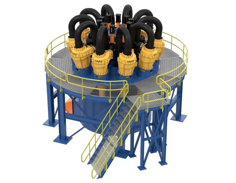
Modular hydrocyclone cluster systems that combine multiple cyclones into a single compact unit. Increase throughput while reducing footprint in classification and separation circuits.
100mm – 660mm per individual cyclone
2 to 16 cyclones per cluster unit
15 – 4,500 m³/h depending on configuration
60 – 250 kPa operating range
Ceramic, rubber, polyurethane, chromium carbide
Classification, desliming, dewatering, separation
Multiple hydrocyclones are arranged in a circular or linear cluster, fed by a common distributor header. Each cyclone operates independently, but the combined unit delivers far higher throughput than a single large cyclone — with better classification efficiency.
Slurry enters the central distributor header, which splits flow evenly across all cyclones in the cluster. Equal feed distribution is critical — uneven splits reduce classification sharpness and cause premature wear on overloaded cyclones.
Each cyclone generates a vortex that separates particles by density and size. Coarse material spirals down to the apex (underflow), while fine particles exit through the vortex finder (overflow). Multiple small cyclones achieve a sharper cut than one large unit.
Overflow and underflow streams from all cyclones are collected in common launders or discharge pipes. The clustered layout reduces floor space by 40–60% compared to equivalent single-cyclone installations.
Combine 4–16 small cyclones to achieve flow rates that would otherwise require a single oversized cyclone. Small cyclones produce a finer, sharper cut point — critical for downstream process efficiency.
Cluster layout compresses the total installation area by 40–60%. No need for separate feed pumps, launders, or support structures for each individual cyclone. Ideal for constrained plant footprints.
Individual cyclones can be isolated and serviced without shutting down the entire cluster. Quick-change liner and spigot assemblies reduce downtime from hours to minutes per cyclone swap.
Ceramic-lined cyclones for high-abrasion feeds. Rubber-lined for impact resistance. Polyurethane for fine-particle desliming. Each liner is selected based on your specific slurry characteristics.
| Application | Cluster Size | Key Requirement |
|---|---|---|
| Grinding Circuit Classification | 4–12 cyclones, 250–500mm | Sharp d80 cut, consistent overflow size |
| Desliming Before Flotation | 6–16 cyclones, 100–250mm | Fine cut point, high volume per m² floor space |
| Dewatering for Tailings | 4–8 cyclones, 350–660mm | Coarse underflow, water recovery from overflow |
| Sand Washing & Classification | 4–8 cyclones, 150–300mm | Consistent gradation, low water loss |
| Mineral Sands Separation | 8–16 cyclones, 100–200mm | Multi-stage separation, high sharpness index |
It depends on your total flow rate and target cut point. Most mineral processing circuits use 4–12 cyclones. We size the cluster based on your feed flow, solids concentration, and desired overflow d80.
Yes. Each cyclone in the cluster has its own isolation valve. You can shut off and service one cyclone while the remaining units continue operating at reduced capacity.
Alumina ceramic liners are the standard for high-abrasion applications (90+ Mohs hardness feeds). Rubber liners are preferred when there is a risk of tramp metal or coarse oversize in the feed.
Depends on feed abrasivity and throughput. Ceramic liners in standard grinding circuits last 2,000–4,000 hours. Rubber liners typically last 1,500–3,000 hours. We provide wear-life estimates for your specific application.
Tell us your flow rate, feed type, and target cut point — we'll design the optimal cluster configuration and provide pricing within 24 hours.
Request Quote → Pumps
Pumps